DFM Fidget Toy
December 2023
Design for manufacturing of an injection-molded fidget toy.
Relevant skills:
This project was designed around the following scenario:
Your customer would like to make the object in batches of 1,000-10,000 per month. At this production rate, products are often injection molded and then assembled with the help of mechanical fixtures. For this project, you will need to make both a pre-production unit and (if applicable) the fixtures needed to assemble it.
The learning objectives for this project were:
-
Design a product to meet injection molding considerations and constraints
-
Design an aluminum mold to be used to form the parts for the product and machine it using a computer numerically controlled (CNC) mill
-
Set up the manufacturing process and optimize the process parameters for injection molding (timing, temperature, shot size, pressures)
-
Manufacture and assemble a batch of products
-
Assess the quality of the manufactured products
The goal for this project was to create a fidget toy that was easy to manufacture using injection molding, did not require any tooling to assemble, and was satisfying to hold and fidget with.
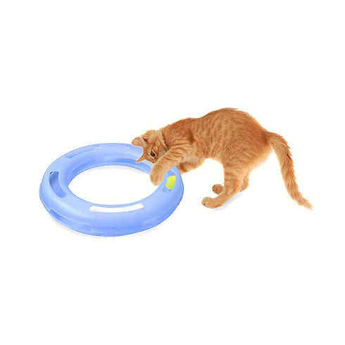
We were inspired by the cat toys that consist of a ball inside a plastic track, like the one shown here.


To ensure that our designs met our design requirements before we began manufacturing, we created several iterations of 3D-printed prototypes.
Through this process, we were able to create a design that was composed of two identical parts to minimize the machining time and material cost, and which could be assembled without even a screwdriver.

One of the primary design challenges that we faced during this project was creating a design with a parting surface that was a single plane, as a more complex parting surface would mean that we would need to face down at least one side of the mold block, which would have increased the machining time (and therefore cost) of our mold. By altering the shape and location of the surfaces that held the steel ball in the track from that of our original design we were able to keep our parting surface low-cost and effective.
Another design challenge that we faced was designing to allow for the machining of the aluminum mold block without as little specialty tooling as possible. Our final design did require some relatively uncommon endmills, particularly the 1/16" ball endmill, 1/16" 5° tapered endmill, and 1/4" 60° mill drill, but we were able to share some of our endmills with other teams, which decreased the cost of purchase. We were also able to avoid needing a corner rounding endmill by changing the shape of the channel that contained the ball from the rounded shape of the original design.


The design of our sprues and air vents was another design challenge. We originally designed our mold to have two sprues for each part, but after performing flow simulations, we realized that this configuration would trap air on the inside of the part and cause two potential locations for weld lines. To avoid this, we changed our mold design to have only one sprue for each part.
The biggest challenge that we faced in this project was optimizing the process parameters on the injection molder. We had kept the volume of our plastic parts small to reduce our production cost by minimizing our machining time and material usage. However, this had the unintended effect of requiring extremely precise timing and shot size during the injection molding. We were unable to consistently meet these specifications with the injection molding machine that was available to us and had to compensate by trimming the excess flash off of some of our parts. This photograph shows most of the attempted injection molded parts. There was less than a second of difference in injection time between the parts with the most flash (top right) and the parts with the most missing volume (bottom left), and all other parameters were kept as consistent as possible.

Here is an exploded view of our final assembly. Because both sides have a hexagonal pocket, twisting them in opposite directions tightens the bolt without any need for external assemblies or tooling, and both sides can accommodate either the bolt or the nut.

Here's a photograph of our finished mold block.
Here's a photograph of a final, assembled fidget toy. While we struggled to produce parts on our injection molder that didn't require extra finishing due to excessive flash, our design did meet most of our goals. It was quick and cheap to machine, and the resulting toy was fun to play with and comfortable to hold in one hand. If we had had access to a more precise injection molder, this design might have been successful. However, to make our design work better for this injection molder, we should have added longer sprues to the mold and possibly included a reservoir for extra plastic to flow into so that we didn't require as much precision to achieve a well-molded part.

Engineering Drawings
This is an engineering drawing of our injection molded part which shows the critical dimensions.


Bill of Materials & Cost Analysis
Here are the bill of materials and cost analysis for our fidget toy. One of them shows the cost of consumables used for each fidget, and the other estimates the cost of mold materials, tooling, and labor.
Consumables

Non-Consumables
